Dissemination material from the Final Public Workshop of the SuCoHS project
The Final Public Workshop of the SuCoHS project was held virtually on 22-23 February 2022. The related dissemination material is available.
The links below will let you download the public versions of the presentations that were given during the Final Public Workshop:
Tuesday 22nd of February 2022
- Introduction to the SuCoHS Project by Tobias Wille, German Aerospace Center (DLR)
- Development of a Highly Complex Composite Nacelle "Inner Fixed Structure" Component Using Automated Fibre Placement and Multifunctional Materials by Daniel Breen, Spirit AeroSystems
- Fire Response of SuCoHS Novel Material in Composite Fuselage Designs: Principles, Manufacturing and Testing by Iñigo Ortiz de Zarate, Aernnova Engineering Division
- On the Feasibility of a New Robotic Alternative to Present Honeycomb Shell Structures in Aircraft Interiors by Paolo Ballocchi, Deepa Jose, Pavlos Tranakidis and Andrew Blackwood, Collins Aerospace
- Panel discussion on “Challenges and Opportunities for Exploiting Composites Demanding High Temperature and Fire Resistance”, presentation 1 (from the consortium) and presentation 2 (from EASA)
Wednesday 23rd of February 2022
Session "Sustainable Materials"
- Fire-related Use of Composite Materials in Helicopter Applications by Manuel Kempf and Martin Lazak, Airbus Helicopters Germany
- Material Development for a High Temperature Resistant Thin Ply Composite Based on a Modified Cyanate Ester Resin by Christian Brauner, University of Applied Sciences and Arts Northwestern Switzerland (FHNW)
- Polyfurfuryl Alcohol Resins in Fire Resistant Applications of Advanced Composite Manufacturing by Hans Hoydonckx, TransFurans Chemicals
Session "Efficient Industrialisation"
- Industrialisation of Thin Ply Composite Manufacturing by Thomas Ricard, North Thin Ply Technology
- Enhanced Manufacturing Solutions for Tailored Composite Structures with Novel Materials and Integrated SHM by Wilco Gerrits, Netherlands Aerospace Centre (NLR)
- Online Tg and Viscosity Monitoring for Advanced Composites Manufacturing by Nikos Pantelelis, Synthesites
Session "End-2-End Analysis"
- Perspective On Integrated Aircraft Health Monitoring by Rafik Hadjria, Safran Tech
- Applications for Embedded FBG Sensors in Composite Lifetime Enhancement and Monitoring by Gideon Langedijk, PhotonFirst
- Enhanced Thermo-mechanical Analysis to Exploit Structural Reserves by Martin Liebisch, German Aerospace Center (DLR)
- Simplified Fire Analysis Methodology to Support Fire Certification Tests by Juan Penche, Aernnova Engineering Division
The recordings of the two sessions of the Final Public Workshop can be seen on YouTube:
The answers to the questions that were asked during the Final Public Workshop are provided below:
- Development of a Highly Complex Composite Nacelle "Inner Fixed Structure" Component Using Automated Fibre Placement and Multifunctional Materials by Daniel Breen, Spirit AeroSystems
Question 1: Do you manage edge sealing at high temperature?
Answer: Standard edge sealant such as Airtech GS-213 can be used up to temperatures of 200°C. The use case demonstrator did not require any initial curing (under vacuum bagging) over 200°C. Most resin systems use a free standing post cure to increase Tg.
Question 2: What is the CFRP material? Thermoset or Thermoplastic? The curing temperature?
Answer: Confidential.
Question 3: Why do you monitor only the Tg during the cure (it seems what we observed in the video)?
Answer: Monitoring the Tg can enable the cure cycle to be reduced. Nikos (Synthesites) will present further details on this technology tomorrow [presentation entitled “Online Tg and Viscosity Monitoring for Advanced Composites Manufacturing” on the 23rd of February 2022, slot 11:30-11:45]. During the project we were able to reduce the cure time of the demonstrator material but altering the cure parameters - this was validated using the Synthesites online monitoring technology.
Question 4: How is the perforation (of CFRP-layers) done?
Answer: An abrasive grit blasting process.
Question 5: Do you see Spirit AeroSystems doing more work on composite IFS?
Answer: Yes for sure; however it is unclear at this moment if the Belfast site or an alternative Spirit site (or both) will continue the development.
- Fire Response of SuCoHS Novel Material in Composite Fuselage Designs: Principles, Manufacturing and Testing by Iñigo Ortiz de Zarate, Aernnova Engineering Division
Question 1: Did you investigate using noodles at the T-intersection?
Answer: No.
Question 2: How did you determine you only needed to carry load for 5 minutes of the 15-minute burn?
Answer: This corresponds to the EASA fire requirements (CS 25J1193 APU compartment). Loads representative of ground condition as per stress analysis considering the APU should be operative for the first 5 minutes and during the remaining 10 minutes stopped conditions for the APU.
Session "Sustainable Materials"
- Fire-related Use of Composite Materials in Helicopter Applications by Manuel Kempf and Martin Lazak, Airbus Helicopters Germany
Question 1: Which of the mentioned certification requirements may/should be challenged without affecting the safety, and which conservatisms are required due to uncertainty?
Answer: The requirements themselves are generally accepted, but the interpretation and the means of compliance are sometimes a matter of discussion. For example, one controversial topic is the selection of the loads to be applied under fire conditions where the current assumptions are clearly on the conservative side. Another matter is the fire test procedure where the same burner that is specified for CS-25 airliners has to be used also for helicopters with their much smaller engines and engine compartments.
Question 2: How does the choice of the insulation material affect the overall design concept?
Answer: This is always a matter of arbitration between different requirements. For example, if a requirement exists to be able to step onto the protection as in the case presented then the insulation material is limited to mechanically robust ones, which in turn are not the most efficient thermal protections and may require a more damage-tolerant design for the structure below.
Question 3: How do the connections within the fire zone (screws, bolts) influence the fire behaviour ? E.g. flame penetration. Are such effects covered by the sealant?
Answer: The sealant that caused the backside ignition is used for fluid tightness and corrosion protection. Direct flame penetration is prevented by the overlapping screw heads which form a kind of labyrinth that the flame will not penetrate. Nevertheless, the screws form a heat bridge which has to be sufficiently insulated or attenuated.
Question 4: In the design shown, regarding the fire protection walls, are these components there to isolate the remaining structure from the heat or are they multifunctional and exposed to mechanical loading at the same time?
Answer: The deck at the bottom of the engine compartment is a structural member which doubles as a firewall. In contrast, the vertical firewalls are used to attach the cowlings and are subject to some aerodynamic loads coming from those, but they primarily serve as fire containment and are not part of the primary structure.
Question 5: Regarding the materials developed in SuCoHS, is their application possible in helicopters? What would be the next steps in the certification scenario?
Answer: Prerequisite for new material qualification is a successful screening campaign which addresses all technical requirements and potential blocking points. Furthermore, the material has to be commercially available from a reliable supplier meeting all required aerospace quality standards. Non-recurring qualification costs of the material need to be evaluated against its benefits (e.g. performance, weight, recurring costs).
- Material Development for a High Temperature Resistant Thin Ply Composite Based on a Modified Cyanate Ester Resin by Christian Brauner, University of Applied Sciences and Arts Northwestern Switzerland (FHNW)
Question 1: Regarding the slide 6: Is it possible to reduce the overall process time by increasing the cooling rate of the post cure process?
Answer: Yes it is possible, we have done investigations to speed up the process. Please look at https://www.sciencedirect.com/science/article/pii/S0263822320331500?via%3Dihub
Question 2: How do you explain the difference between BMI and CE because here we don't see the mechanical properties of BMI ?
Answer: The question is related to the inter laminar shear strength values which are shown on slide 14. The results shown is a comprehensive study related to aging of specimens at 250°C and 300°C over a duration of 4 weeks. Samples have been taken out of the oven every week and have been tested at RT and higher temperature to understand the effect of degradation.
- Polyfurfuryl Alcohol Resins in Fire Resistant Applications of Advanced Composite Manufacturing by Hans Hoydonckx, TransFurans Chemicals
Question: Can you say something about the scatter of the results and the scope of the tests? (slide 18)
Answer: The scope of the ILSS testing was to investigate the sensitivity of matrix material temperature dependency on the composite behaviour, since this test is simple and a good indicator for that. Further, it allowed us to compare the behaviour over temperature for several materials and cure cycles. The scatter of the results was within the domain of typical magnitudes, approx. standard deviations of 1-2%.
Session "Efficient Industrialisation"
- Industrialisation of Thin Ply Composite Manufacturing by Thomas Ricard, North Thin Ply Technology
Question 1: What are your limits in terms of volume production?
Answer: We have 2 prepreg lines of 300mm and 450mm width. These lines can operate at 4 linear meters per minute on 3 shifts. Basic mathematics and good safety margins would result in an annual capability of processing about 40 tons of carbon fiber if the prepreg produced was 50gsm or 250 tons if it was 300gsm.
Question 2: There is a significant gain of mechanical performance by using the thin ply material. In case we aim for the same mechanical performance, how would it translate into the cost reduction of the composite material?
Answer: Using thin plies results in significant gains in mechanical properties such as tensile or compressive strength, fatigue... This gain in performance could either be used to increase the coefficient of safety or to reduce the weight of the structure. A lighter structure would obviously reduce the overall material cost even if a lighter prepreg has a slightly higher price per mass.
The most significant economical gain can be achieved by adopting an integrated approach to take benefit of automation and kitting production and by designing hybrid structures where thin plies are used in the most critical areas (stress concentration zone, load introduction, holes, ribs...) in combination with heavier plies in the less demanding parts of the structures.
- Enhanced Manufacturing Solutions for Tailored Composite Structures with Novel Materials and Integrated SHM by Wilco Gerrits, Netherlands Aerospace Centre (NLR)
Question 1: What heating mechanism was used during the AFP?
Answer: For this material we have used the infrared heater of the AFP machine.
Question 2: Do you embed fibers by AFP? If yes, how do you not break them?
Answer: Yes, as shown in the movies, optical fibres were positioned by the AFP machine. After positioning and curing, the optical fibres will be embedded into the laminate. For AFP, special guides were developed to prevent damage to the fibres during positioning. After completion of the laminate, small tubes were applied around the optical fibres, covering the not embedded part of the optical fibre (the outcoming length with connector outside the final product). The component side of this tube was also embedded into the laminate for approximately 10 mm, to allow for resin fill, resulting in improved stability at the point where the optical fibre exits the laminate (egress point after machining). The tube with optical fibre, filled with cured resin, stabilizes and protects the fragile optical fibre from the egress point of the composite product up to the connector for the interrogator.
Question 3: Could you please confirm if AFP was used itself to create stiffeners or "just" to reinforce the already existing stiffeners by placing tapes on top?
Answer: AFP was used to create the whole stiffener, from bottom to top, as a monolithic structure.
Question 4: Was there any special arrangement to deal with the egress point of the embedded fibres?
Answer: A small tube (outside diameter = 1 mm) was applied around the optical fibre and embedded into the laminate for approximately 10 mm. This way the optical fibre is protected against damage from egress point to connector.
- Online Tg and Viscosity Monitoring for Advanced Composites Manufacturing by Nikos Pantelelis, Synthesites
Question 1: Why is there never Tg value below 120°C ?
Answer: (following this comment, some graphs were updated in the corresponding presentation to reflect the process window in which the Online Tg calibration was validated)
Online Tg is being calculated only after gelation as this is of interest to the composites manufacturers. Before gelation, when the resin is liquid, the viscosity is being estimated online.
Question 2: The cure simulator may not be installed in very complex shapes. What is the possible exploitation for such critical areas in terms of quality control?
Answer: Actually the cure simulator can be used independently of the shape of the part, as it just requires a temperature measurement from a thermocouple of Pt sensor. In complex shapes, the disposable sensors are also recommended as they give a very representative measurement of both temperature and curing without creating too much disturbance. The durable sensors have more restrictions with respect to part shapes and tooling but they provide a very reliable and cost effective solution for repetitive use.
Question 3: Can only the Tg monitoring be performed, or can this be elaborated to other properties e.g. for mechanical performance? Can the calibration be done accordingly?
Answer: We have correlated resistivity to Tg, degree of cure, viscosity, mixing ratio and resin aging. We expect that other resin properties such as modulus could be also correlated to resistivity.
Question 4: Is there any issue with the pressure applied on the sensor when it is introduced in the composite?
Answer: Our sensors are not affected either by the hydraulic resin pressure or the fibre compaction pressure. We have used our sensors successfully at High Pressure Compression RTM with pressures reaching 200 bar without any issues.
Lab tour
Question : Would it be possible to show also the strains in the fiber braggs?
Answer: The small panel used during the live lab tour didn’t have integrated FBGs. Yet, our SuCoHS test structures are equipped with FBGs allowing for strain monitoring.
Session "End-2-End Analysis"
- Perspective On Integrated Aircraft Health Monitoring by Rafik Hadjria, Safran Tech
Question 1: Could you please explain which particular damages shall be detected by the SHM and by which accuracy?
Answer: The damage is either crack and decision of the resin and fiber. We have an interest too to assess stiffness degradation (due to impact event).
Question 2: Pity that there was no indication of how well the SHM correlates with other types of sensors.
Answer: We haven't launched yet experiments related to SHM. Actually, we are focusing mainly about RTM. We expect to have initial results about SHM at the end of 2022.
Question 3: What are the forecast sensors technologies that are used in the MORPHO project ?
Answer: The identified technologies from the partners are: FO-FBG, PZT, dielectric sensors.
- Applications for Embedded FBG sensors in composite lifetime enhancement and monitoring by Gideon Langedijk, PhotonFirst
Answers provided by Frank Grooteman, Netherlands Aerospace Centre (NLR)
Question 1: What is the dimension of the sensor node at 1 MHz samling rate?
Answer: It is approximately 15x15 mm. Recently high sample rate interrogators have become available for FBGs as well, with which we hope to achieve the same accuracy.
Question 2: Could you please further describe or quantify the improved impact localisation for higher frequency measurements?
Answer: Depending on the wave speed you can compute the distance travelled by the wave during one sample. This gives an indication of the accuracy that can be achieved. The high sample rates also allows to capture Lamb waves.
Question 3: Was there any issue with keeping the embedded fibres in place during the curing cycle? For example when the resin viscosity drops, were they able to move around?
Answer: A fully embedded fibre will become part of the UD CF ply and therefore "fixed" inbetween the CF's. We haven't discovered moving optical fibres during curing.
- Enhanced Thermo-mechanical Analysis to Exploit Structural Reserves by Martin Liebisch, German Aerospace Center (DLR)
Question 1: How accurate is the surrogate?
Answer: It depends on the variation of the result parameters and the number of analysis conducted. For Local Buckling as global structural phenomenon, where the sensitivity to variations of the temperature field is low, errors of approximately 1% were determined using the leave-one-out methodology. However, the number of conducted analysis, here 100, is relatively low for the number of parameters and the high parameter space. Failure as local phenomenon is much more sensitive to temperature variation. Similar surrogate errors could be achieved by significantly smaller parameter space and higher number of analysis.
Question 2: How did you assess the strength and how precise is such an assessment at high temperature?
Answer: We used First-Ply-Failure and compared the criteria of Hashin, Puck and Cuntze. Similar for all and as expected, the sensitivity of transverse failure to temperature dominated the resulting failure modes and lead to low failure loads. We will further investigate on the applicability of such criteria at temperatures up to Tg. Within our initial structural test, we have further seen loads at temperatures significantly above transverse failure prediction. Following from this, it is concluded that failure assessment at laminate level could be more proposing.
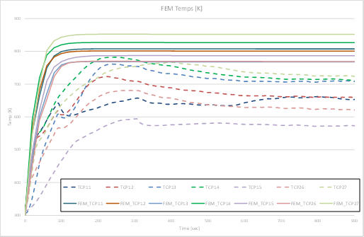
- Simplified Fire Analysis Methodology to Support Fire Certification Tests by Juan Penche, Aernnova Engineering Division
Question 1: Do you think that, if you consider delamination within the structure, the difference between experiment and FEA will converge?
Answer: Yes. At least we expect an increase of the accuracy. The appearance of delaminations during the degradation of the composite forms thermal barriers that prevent the heat from reaching the back surface of the specimen and releasing to the ambient. In fact, looking at the temperature measures from tests (dashed lines, slide 12) they show a decrease after the temperature peak (probably due to those thermal barriers) that the model is not able to reproduce accurately.
Question 2: Where is the limit of your model?
Answer: Theoretically, if we have all the required material thermal and mechanical properties, we could perform a simulation to predict its reaction under fire condition. However, the real constraint of the model is that, in the medium-term, it is not going to substitute the necessity of performing a certification test to validate a structure against fire.
Question 3: What would be your idea of how many materials you would need to test to have a security for your model?
Answer: It is difficult to predict. So far, we have correlated this model with just one material and with just one test. To gain confidence in this model we should perform this correlation with, at least, the most used composite materials in aeronautics.
Question 4: How long did the analysis of each layer take?
Answer: The thermal model took 6h to run whereas the mechanical model took 13h using an equip with 9cores per process and enough memory (>100GB). The mechanical model lasts twice as long as the thermal model because it has to read temperature and degradation values from thermal model.
DISCLAIMER
The information, statements and opinions in the above dissemination material are personal views of the individuals involved in the SuCoHS project and do not necessarily reflect the views of the SuCoHS consortium as a whole, nor of the European Commission. None of them shall be liable for any use that may be made of the information contained herein.